Generative Design – The Future of Feature Modeling
Definition
Generative Design is a new tool introduced in Solid Edge ST10 where you can define a specific material, design space, permissible loads and constraints and a target weight and the topology optimization engine automagically computes the geometric solution.
Topology optimization determines the most efficient material distribution to meet the exact performance requirements of a part. It takes into consideration the given space allowed, load conditions of the part and maximum stresses allowed in the material.
It doesn’t matter if the model was created using sketch based features or synchronous or was even an imported IGES, STEP, ACIS or Parasolid file. The Generative Design tool in Solid Edge adds and removes material between the design features to make the part optimally stiff and lightweight. It also smoothens and blends surfaces to minimize stress concentrations.
Setting your Expectations
Right off the bat I’d like to debunk the myth that generative design mimics nature’s evolutionary approach to design or for that matter an overhyped cliché that generative design mimics the way organisms evolve in the natural world.
To a great extent both nature and Frustum’s core technology TrueSOLID which powers generative design in Solid Edge are based on the principle of minimizing material without compromising on strength and performance of the object, but the similarities end there and should not be exaggerated further.
The fundamental difference lies in the way how nature’s designs evolve from the ground up, out of nowhere and can take any organic form, whereas in generative design you start with a seed design, a basic form for the machine part, most probably a prismatic shape, which generative design further optimizes for topology. So it works more in a top-down fashion. In short, nature is not in the business of optimizing existing designs. We as designers are.
Get Your Feet Wet
Download and open this Solid Edge ST10 part of a lazily modeled bicycle frame which is more like a lump and is purposely not created as a frame structure. I am by no means an expert on this but it is my understanding that if you want to relish the benefits of generative design do not feed it an already optimized part.

The above model primarily conveys the key connection points on the frame when it will live as part of the bicycle assembly and the rest is a lump or mass that you generously leave for the optimizer to play with.
On the Generative Design tab of the ribbon, click the ‘Create Generative Study’ button. The material ‘Stainless Steel, 420’ will be automatically assigned to the part. This along with a host of other settings come from the Options dialog of Solid Edge. See the tab for Generative Design.

 Design Space
Click this button on the ribbon which highlights the entire model. Select Accept  or simply right click.
In a different study where multibodies are present in the model space, you can cancel the suggested selection and pick the desired one.
 Preserve Regions
Click this button next and select:
- The cylindrical surfaces on the upper side.
- Caps of the upper cylinders.
- Cylindrical surfaces on the lower side.
- Holes in the lower cylinders.

Also specify 2 as the offset value.
With this you are asking to optimize everything but these regions which should remain intact since they will be used for connecting the rear axle, paddle assembly spindle on the lower side and the seat and handle parts on the top side in the final bicycle assembly.
Right click to finish this step.
 Force
Force
The shape of a machine part is the tangible visualization of the forces acting upon it and we humans derive the basic shape of a machine part based on our previous experience and training about the rules of engineering design with material science thrown in. We are never allowed to lose sight of the Form, Fit and Function triad. Generative Design takes it ahead and optimizes the topology as served, taking into consideration the constraints like preserving specified regions and allowable stresses.
Click the Force button on the ribbon bar and pick the top end caps of the cylinders as shown below.

 If the unit does not appear in the edit box for force value, check this setting in the Solid Edge Options General tab

Also note that the unit and the decimal precision comes from the Units tab of the Options dialog.

Click the Flip Direction button  on the CommandBar to have the force vector pointing downwards instead of it pointing away from the model by default.
Also explore the Symbol Size/Spacing button  on the CommandBar to tweak the display of the force indicators on the model.
Right click to finish this step.
 Fixed
Fixed
Click this button on the ribbon and select the cylindrical holes in the lower portion of the frame lump each for the rear axle and the spindle.

Spherical indicators will appear to confirm which faces are fixed.
Right click to finish this step as well.
 Generate
Click this button to generate the optimized model of the bike frame. The Generate Study dialog appears with default settings of Study Quality = 5 and Target Mass Reduction = 50%
Click the Generate button in the dialog without changing any default setting and wait as the progress bar indicates whats happening. Note during your wait that one of the steps mentioned is meshing. After some time depending on your computer speed, another dialog appears which can be closed to display the optimized result in the modeling area.
This is just a glimpse of the bike frame shape that it spits out with a target mass reduction of 50%
Note how Solid Edge has preserved the regions around the cylindrical portions you specified and removed mass from the remaining portion of the body.

If you start with existing designs and ideas, you can be creative at a higher rate. For humans this could amount to plagiarism but for a computer loaded with Solid Edge having close to artificial intelligence capabilities like these, it simply amounts to churning out design variations using brute force method.
Click the Generate button on the ribbon bar again and drag the Target Mass slider to 75%. This will result in a thinner frame similar to the one shown above and you should decide if it is acceptable from manufacturing or aesthetic viewpoints.
Keeping the same target of 75% mass reduction if you slide the Study Quality to a value of 50 or 100 and be patient enough for the generator to meditate longer over the optimization, the result could be more acceptable and aesthetically pleasing.

Also note how truss like elements are introduced, generating a web structure assuring rigidity and strength which is truly remarkable. This is where Generative Design surpasses common human imagination and such results cannot be envisioned by designers without having profound knowledge and previous experience with organic designs.
Under The Hood
Let’s take some time out to ponder how Generative Design in Solid Edge accomplishes this seemingly magical feat.
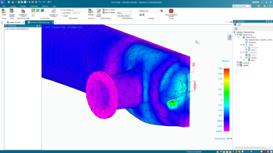
At the heart of such calculations is analysis of the frame body we started with. If you have a Simulation license in Solid Edge, it is possible to generate a plot of the stresses from a linear static study found on the Simulation tab of the ribbon bar.

Note that the magenta regions are relatively safer than the blue ones while the green patches indicate higher concentration of stress.
Superimposing the optimized model on the FEA plot reveals how it has used this information to add mass in areas of higher stress concentration and removing from where it is safest to do so.

 Also remember that in Generative Design more mass is added where you have sought to preserve regions.
The Generative Design Pane
While you were busy pushing the Generative Design optimizer to its limits using your state of the art supercomputer, kicking all those dormant CPU cores out of slumber, Solid Edge was silently gathering all the information you fed into a nice hierarchical tree structure in the Generative Design pane. Initially this pane may appear collapsed on the left side of the Solid Edge window.

Click the nodes on the tree and then click the callout that appears on the model again to tweak any of the parameters like preserved regions, force value and its direction and the fixed faces or features specified earlier. You can also delete any parameter and redefine it from scratch. And it goes without saying that you must click the Generate button on the ribbon again to see the optimized result using the changed settings.
 To start over and create a new Generative Design study, right click on the main node in the tree and select Delete form the context menu. With a Generative Design Pro license though this is not required, since the Pro license enables you to save multiple Gen Design studies and navigate back and forth them. Besides this the Pro license comes with all the extra features like applying pressure and torque, manufacturing settings and examining stress in the optimized model. See @DavidChadwick‘s comments at the end of the article to see the full list of features that come with the Gen Design Pro license.
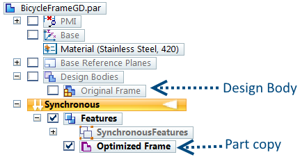
Also note that you can show/hide either the original design body and the optimized body from the part pathfinder as below:

Epilog
This was a rudimentary design optimization study and several factors were either generalized or left out for a bicycle frame design, but it gives a fair idea and insight into the new technology introduced in Solid Edge ST10.
The result of topology optimization is a mesh body which can be readily fed to a 3D printer. Before doing this, the mesh can further be manipulated using the new mesh editing capabilities of Solid Edge using the same commands that you have been using for solid modeling.
Meanwhile, note that the direction of force applied at the handle point on the frame need not necessarily be pointing vertically downwards but at an angle and parallel to the front suspension.
In the upcoming blog articles, I will show:
• How you can use the steering wheel to change direction of the force vector.
besides these:
• How to harness the power of Synchronous Technology in Generative Design studies.
• How the choice of preserved regions and fixed faces affect the outcome of optimizations drastically.
• How to perform convergent modeling operations on the optimized mesh.
Until then, let’s optimize, let’s sync, let’s converge…