Exposing Variables in Solid Edge and its Applications
The variable table in Solid Edge displays, defines, and manipulates design variables and functional relationships between the variables. The variable table can also be looked upon as a window for the outside world into a document and this is especially facilitated by the Expose feature.
Beginning V16, the variable table sported a new column called Expose. For those who use the Solid Edge API could access the variable names and values programmatically even without the Expose functionality. This post shows how to expose variables and about the various scenarios where this feature could be used by an end user who is not necessarily a programmer.
Expose a Variable
Create a simple box by extruding a dimensioned rectangle, then select Variables from the Variables Panel on the Tools tab. The variable table will be seen containing at least three dimension variables. Rename them appropriately as Length, Width and Height.
Observe the column – Expose – with only check boxes in it.
Note: You can re-order the columns by dragging the header and dropping it ahead or after any other column.
Click in the check boxes for all three variables and make sure they are checked ON.
By clicking in the check boxes, you have exposed the variables to the world outside this part.

File Properties
Once the variables are exposed, they are listed in the Document’s properties.
Click the Solid Edge Application Button > Properties > File Properties and take the Custom tab. You will find that the three exposed variables are listed as Text type.

Callout in the Draft
These figures can also be pulled into a draft file in a Callout 
In the Callout dialog, click the Property Text button 
In the Select Property Text dialog, click Named reference from the drop down list.

You will find the exposed variables listed in the Properties list below.
The callout text would appear something as below:
%{Length/CP|AHU_KA700.par} x %{Width/CP|AHU_KA700.par} x %{Height/CP|AHU_KA700.par}
The variable name is tightly coupled to the file name in the text indicating the values in the callout text will always update since they have reference to the part file.
Applications in Assembly
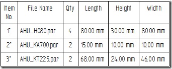
Recently I was contacted by a AHU (Air Handling Unit) designer who would create assemblies out of only boxes of various sizes which represent the place holders of the various components inside an AHU.
The assembly was required to reflect the quantity and sizes of the boxes to appear in the BOM. Neither of these was a problem with Expose Variables.

The designer would simply expose the Length, Width and Height variables for each of the box part files.
The Parts List in Draft environment also supports exposed variables.
In the Parts List properties dialog, take the Columns tab. In the Properties list, select the Length, Width, Height items and click Add Column to add the exposed variables to the Parts List column. This would result in a Parts List as shown in image above.
Adding a column for a user-defined variable such as the space taken up by the components of the boxes is just as easy. Back to the part document and inside the variable table, add a new variable called BoxVolume and specify “= Length * Width * Height” as the formula without the quotes. Not to mention, Expose the variable to be able to add it to the Callout or Parts List or have it listed as a Custom property.

Comments