CAD is Converging and You Are In Deep

Whether you are an expert designer or a seasoned draughtsman, an automation programmer or a CAD manager, keeping abreast of the latest ways in which your CAD program can create or manipulate geometry goes a long way toward understanding why they appear and behave differently from what they did a few years ago.
Gone are the days when scanned data processing programs lived separately from BRep geometry handling mainstream CAD programs and handshaked through converters. Analysis is no longer a downstream process nor organic shapes in designs ought to be avoided because they pose manufacturability issues or involve high costs. All these seemingly disparate technologies have converged, not allowing to pardon yourself for living in oblivion because you should know – you are in deep.
Yes, Solid Edge has been incorporating several bleeding edge model creation and manipulation technologies over the last two releases. This article touches upon the most prominent ones and how they are converging elegantly but with breathtaking speed at the same time.
Feature Based Modeling is as old as modern CAD and discussing its merits appears too olde worlde these days. All the limitations and pitfalls of feature based modeling are acknowledged and well documented but it has survived to date in spite of its drawbacks.
Direct Editing overcame the shortcomings of feature based modeling. Synchronous Technology is no longer in the realms of innovation but is highly evolved, matured and has become mainstream.
The greatest strengths of Solid Edge has been in building on top of existing technologies or merging newer techniques with existing ones. Direct editing appeared on the scene as a revolutionary alternative to circumvent the perils of feature based modeling, but Synchronous Technology seamlesslyintegrated direct editing with the prevalent history based workflow with a flair that enables designers today to switch between the two from a simple context menu without noticing the flip.
Similarly, a gamut of reverse engineering tools which primarily operate on objects that have mesh-type geometry, have been added to Solid Edge working seamlessly and taking advantage of the existing surfacing tools, sketch driven features and synchronous editing capabilities.
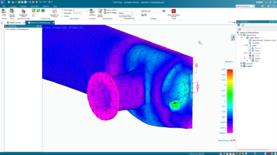
The image below shows the primary difference between BRep and mesh geometries:

Mesh Editing – Just two versions ago Solid Edge could barely interact with imported mesh models. Users could neither select any geometry nor manipulate it by any means.
ST9 introduced reverse engineering focusing on extracting surfaces from a mesh file and converting them to usable surfaces which subsequently can be converted to a solid model.
Reverse Engineering tools in Solid Edge let you create surfaces from the mesh data using manual and automatic methods. You can further save a great deal of time using the powerful set of surfacing commands available on its dedicated ribbon tab.

Products like Smap 3D and Imageware existed prior to this, but the ease of handling meshes right inside the Solid Edge environment is more convenient and hassle free. Besides ease of use it is also possible to create parametric features like holes and fillets in the mesh geometry something which was beyond imagination a few years ago.
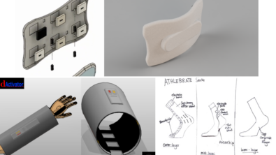
Generative Design is the most happening ‘futuristic’ modeling technique which is available right now and right inside Solid Edge. Generative Design in Solid Edge autonomously generates a number of design alternatives given a set of constraints. It is a kind of Goal Seek on steroids but not limited to crunching numbers within a stipulated range but extrapolates beyond the imagination of the human mind to give virtually unlimited number of design possibilities which you can choose from. The output of generative design are mesh models – so you catch the drift.
Additive Manufacturing is directly related to CAD and influences design in many ways. 3D printing freed designers from the leashes of designing prismatic parts. Easily machinable parts was a designers top priority and was deeply engraved in the thought process. Prismatic parts lend themselves to automation to a certain extent, but manufacturability was a major constriction.
Advancements in Rapid Prototyping have turned manufacturing topsy-turvy in a short span of time and Solid Edge makes a easy job of 3D printing by sporting an array of tools that can be used out of the box.
3D printing which is the foremost technique for additive manufacturing today welcomes mesh models with an open heart which bodes well for generative design. This is an epitome of symbiosis.

Convergent Modeling is the umbrella term which brings together Generative Design, Reverse Engineering and the ability to work with mesh data seamlessly using Synchronous and feature-based modeling methods with no data conversion involved.

In essence, Convergent Modeling is:
- A single geometric modeling component with a unified set of modeling functions for facet models and classic BReps.
- Seamless integration with no delegation to an add-on modeling component.
- No need to convert between BReps and facets.
- Freedom to model with classic BRep or facet models or a combination of the two.
Without a doubt each tool as a standalone entity is immensely useful for an individual’s domain or trade but together these new generation of geometry creation and manipulation methods create what I would like to call – Design Synergy !
In the the forthcoming blog posts I will engage you in greater details into examples which you can work out for yourself on each component of convergent modeling. It’s a challenge learning a bewildering number of new tools but it will be fun beating them together.
Until then.. Let’s Sync, Let’s Converge…

Comments