Building Something
 I decided to just build something. I’m starting simple, with a piece of furniture – a piano bench. I’m going to do as much of this as makes sense in Synchronous. I’ve probably got about 2-3 hours into this, which included some stumbling around. It’s an assembly, not too complicated, but I learned some things, and came up with some questions.
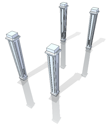
 I started with one of the legs.If you look close, you can see the green sketches that I started with. I didn’t have any idea if it would actually work to sweep a profile around a square where the profile sits exactly on the axis down the middle of the part, but it worked, and i was off to a successful start.
The original sketch was obviously too short, and I had to adjust the finished part up several inches. I just windowed around the top part and the beveled detail, and moved it all up. I originally tried to do it with dimensions, and failed pretty spectacularly at that, so I just used the steering wheel instead, with all of the top faces selected. I also used the “Tip” option so that the angle of the main faces changed as the leg got taller.
Next I just sketched a little groove, made a cut, and filled it with some rounds. I wanted to make the rounds Ordered features, but then I couldn’t do the pattern as a synch feature. So I just moved the rounds back to Synch, mirrored one groove and the rounds, then made a circular pattern with the mirror.
One of the ideas I want to test with working through some real models is that with ST, it doesn’t really matter how you get to your end geometry, just that the geometry is correct. I’ll figure out of this is true or not in realistic models.
 The next item was just the bench top, with a router groove around the edge. Simple enough.
I used a full circle to sweep around the routed quarter round. Then I wanted to edit the width. I’m getting an education on selecting groups of faces to make edits easier. I’m also seeing that editing shapes with arcs is a universally difficult task. It was difficult in AutoCAD, it was difficult in SolidWorks, and its difficult here in Solid Edge as well. I’ve got another part later that I’ll bring out to show more exactly what I mean. Tying down radius dimensions with locked dimensions seems to be a key, as does adding the round faces to the selection set. Sometimes editing in the sketch is equally difficult, with too many possible parameters changing.
 Next is the bench skirt. I’ve been pretty successful so far with sweeping profiles around a rectangular path, so I stuck with that method for this part. I sketched a rectangle and then added the molding trim profile to the bottom. This gave me two short straight lines at the bottom of the sweep profile. The problem with this was that one of the lines was not exactly horizontal, so the faces it produced were a bit wonky. Since you can’t go back and fix the sketch in a situation like that, I fixed it by deleting faces on the bottom of the part. Of course you have to delete the correct faces, or you will wind up with a wonky bottom face instead of a flat face. So I had to do this a couple of times to get it right. Fortunately, Solid Edge has a pretty good Undo feature.
My recommendation is that whenever you have lines that are supposed to be colinear, just delete one of them and make it a single line. There is much less to go wrong in that situation.
 Next was assembling some of the parts. I like the Solid Edge method with the Part Library. It allows you to just bring parts in, and the little preview window at the bottom is very nice, since it’s also dynamic, and lets you pre-define the position of the part before you bring it in. Thoughtfully done, and very useful.
Flash fit is another one of my favorites. Very nice. But I’ll get to that stuff later.
The first part I brought in was a leg. After I brought it in, I selected it and used the Steering Wheel to move it to one corner of the bench. I didn’t know exactly how big it was going to be, so I just guessed. Should be able to adjust it later anyway. I used the Steering Wheel to move the leg in both directions. Now I guess I was assuming that the leg started out lined up on the origin, which may not have been true.
Anyway, I mirrored the position of one leg, then mirrored the other two. I knew I was going to put some support braces in, but wasn’t sure how to create the mating features. The leg is symmetrical, but would the mating features also be symmetrical? How would I do that? I was going to have to solve that problem later.
And I guess I’m going to have to come back later and tell the rest of the story.
How would you have done this differently up to this point?


Comments