Alternate Reality: 51 uses of the ALT key in Solid Edge
Written by: Tushar Suradkar
Straight off the bat the first use that comes to mind is Alt + RMB for View Fit.
which is used frequently in conjunction with Alt + RMB Drag used for Zoom Area.
Further, in the Draft environment, Alt + Click on a callout or leader to add any number of extra vertices. Vertices are edit points that can be used to manipulate the leader line for e.g. creating a jog, etc.

Also Alt + Click on a curve in the Draft or the Sketcher to add or remove Edit Points on the curve.
Annotations can be associative or non-associative. An associative annotation moves when the element it is connected to moves. Make a connected annotation non-associative by pressing the Alt key while dragging the terminator handle off the element
Alternatively (no pun intended) move a leader line connection point to free space or to another element yet retaining associativity with the first element, by pressing the Alt+Ctrl keys while dragging the terminator handle.
When placing a Smart Dimension, keeping the Alt key pressed changes the appearance of the dimension. For e,g, the arc extends when placing the radius dimension.

Tushar is a Solid Edge blogger and programmer for 23 yrs and manages his single-person consultancy by the name CADVertex Solutions that offers custom solution development using the Solid Edge API.

Jogs can be added on projection lines of linear dimension using the Alt + Click.

Use Alt + Click to add one or more jogs to a selected coordinate dimension as below:

Alt + Click a dimension value to suppress the display of the dimension value edit box.
Count = 10
Conversely, Alt+Clicking anywhere on a dimension will bring up the dimension value edit box saving the hassle of aiming the mouse pointer at the text. This applies to PMI and also to dimensions in the Sketcher and Draft environments.
In the Draft environment, click the Select tool and Alt + Click to create a polygon fence around elements for selection.

Use Alt+drag to detach a PMI dimension or annotation from one model element and attach it to a different model element.

When a feature to which a dimension is added is deleted or suppressed, the dimension is orphaned and dangles as indicated with a brown color. Alt + Drag the handle for the extension line and drop it on to a edge or point to bring it back to life.

The grid helps drawing and modifying elements relative to known positions in the working window. Alt+X displays the X and Y coordinate input boxes, with the cursor in the X box while Alt+Y displays the X and Y coordinate input boxes, with the cursor in the Y box.

In wire harness, the path is a curve but the Alt key provides more options to the path than a simple curve in the Sketcher or Draft.
Alt + Click the location along the path where to add a point along the path.

To add a point to the end of the path, Alt + Click a location in free space where you want to add the point.

Alt + Click a point on the path to remove the point. When edit points are removed, the control vertex points move and the shape of the path changes. This holds true for points on a curve created using the Keypoint Curve command in the sketcher and simply the Curve command in the draft environment too.

Count = 20
With annotation alignment shapes, disconnect an annotation from an alignment shape by pressing Alt and then selecting the annotation border. Re-attach it by dragging the annotation on to the shape. And jogs can also be createdon the alignment line using Alt+Click.

A quick way to set the center of rotation during view rotation is to press the middle mouse button and select a point or face to set the point about which to rotate the model.
Press the Alt key while selecting the middle mouse button to cancel.

IntelliSketch does not recognize any relationships while holding the Alt key.
Release the Alt key to re-activate IntelliSketch.
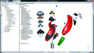
In a Fastener System balloon stack, edit individual balloons in the stack by pressing the Alt key while locating and click the first balloon to modify.

Add or modify the prefix and suffix text of one or more balloons in a fastener system balloon stack by first selecting the stack and then pressing Alt while selecting the balloon to edit.

For Centerlines, Alt + Drag the center line handle to detach and also to re-attach it back.
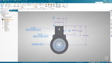
As shown below, press the Alt key while dragging a single dimension (A) in an alignment set (B) to move only that dimension.

When inserting callouts for blocks with custom properties like Cost, Material, etc. sometimes the actual text may appear as ‘Error: Not Connected’. This can be resolved by Alt+dragging the callout handle and dropping it anywhere on the block.

Alt + Middle Click also fits the view to the screen.
Alt + Middle Drag also invokes the Zoom Area command.
Commands on the Ribbon bar can be accessed using the keyboard by tapping the Alt key which displays the key shortcuts for each tab, pressing which the Tab is activated and further key strokes required to access the commands are displayed.
The following work flow demonstrates the Zoom Fit command issued by Alt V F

Solid Edge is smart enough to add a shortcut key even for custom added ribbon buttons, so you can still use the Alt key (Alt C R for revision cloud) as seen below:

Note that its Alt V F and Alt C R and not Alt+C+R since the keys are not pressed in combination with Alt but in succession.
You can change the leader line attachment point using snap points displayed on the feature control frame. Pressing Alt while dragging the point (C) displays the snap points so you can connect to them.

Alt + Z invokes the Zoom tool 
Upon invoking the Zool tool:
• Left click to Zoom In
• Right click to Zoom Out
• Left Drag to Zoom Area
• Right Drag for Dynamic Pan
Two more uses by Imi from the comments section:
Alt + F5 restores the previous view.
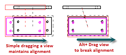
Alt + Dragging a view disrupts or breaks the alignment with its parent view.

Ultimately, press Alt + F4 to quit Solid Edge !
Count = 37
The list will be updated as and when I come across new uses for the Alt key in Solid Edge or when newer versions of Solid Edge bring in more uses to the Alt key.
Tushar is a Solid Edge blogger and programmer for 23 yrs and manages his single-person consultancy by the name CADVertex Solutions that offers custom solution development using the Solid Edge API.
Write to him at Tushar.Suradkar@Gmail.com