3D Geometry API – A Gentle Introduction
Among tangible or visible geometric elements, the prominently accessed collections in a Part or Sheetmetal document are the Features, Sketches, Profiles, PMI and the Reference Planes. The most sought after automation requirements include parametric updating of models or creation of simple parts involving sketches that are extruded or revolved.
It is rare for a designer who is also typically a Mechanical guy having specialized as an automation programmer caring to think about diving into low level geometry like the faces, edges and vertices to manipulate model geometry in a more powerful and direct manner.
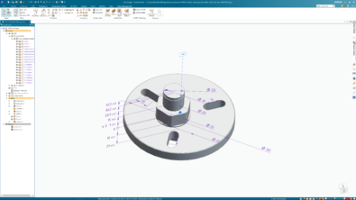
But once you know how to extract and use it, the possibilities are endless. Some common examples would be custom composite holes or Sheetmetal punch shapes. A scenario of a custom composite hole would be a .150 diameter counterbore with a depth of .200. At the bottom of the counterbore is a thru hole of .050 diameter with a nearside countersink of .070 diameter.

Although this article does not aim to show you all the geometric calculations and APIs involved in achieving such composite holes, it is a beginning in the right direction.
Note the additional Solid Edge Geometry reference that must be added which provides for the meaty part of the API involved in 3D geometry access and manipulation:

Faces and Edges can be accessed for the entire model using the workflow below:
Dim seApp As SolidEdgeFramework.Application = GetActiveObject(“SolidEdge.Application”)

Dim seDoc As SolidEdgePart.PartDocument = seApp.ActiveDocument


Dim seModel As Model = seDoc.Models(0)

Dim seBody As Body = seModel.Body


Dim seFaces As Faces = seBody.Faces(FeatureTopologyQueryTypeConstants.igQueryAll)

Dim seEdges As Edges = seBody.Edges(FeatureTopologyQueryTypeConstants.igQueryAll)
The FeatureTopologyQueryTypeConstants come from the SolidEdgeGeometry reference.
The other possible filters are:

You can either query all faces or edges using igQueryAll and then check each one using its Geometry property in a loop as below:
Dim seFace As Face


For i As Integer = 0 To seFaces.Count – 1

seFace = seFaces.Item(i)

  If TypeOf (seFace.Geometry) Is SolidEdgeGeometry.Plane Then

    Debug.WriteLine(seFace.Area)

  End If

Next
Similarly, to check edges you use the Geometry property as shown next.
 Note how the geometry is compared with Line and not with Line2D from the SolidEdgeFrameworkSupport library. These two are entirely different species.
For Each seEdge As Edge In seEdges

  If TypeOf seEdge.Geometry Is Line Then

    Debug.WriteLine(GetEdgeLength(seEdge))

  End If

Next
Where the GetEdgeLength function looks like:
Public Function GetEdgeLength(ByVal seEdge As Edge) As Double

  Dim StartVertex As Vertex = seEdge.StartVertex()

  Dim EndVertex As Vertex = seEdge.EndVertex


  Dim StartVertexCoordinates(2) As Double

  StartVertex.GetPointData(StartVertexCoordinates)


  Dim EndVertexCoordinates(2) As Double

  EndVertex.GetPointData(EndVertexCoordinates)


  Dim StartX As Double = StartVertexCoordinates(0)

  Dim StartY As Double = StartVertexCoordinates(1)

  Dim StartZ As Double = StartVertexCoordinates(2)


  Dim EndX As Double = EndVertexCoordinates(0)

  Dim EndY As Double = EndVertexCoordinates(1)

  Dim EndZ As Double = EndVertexCoordinates(2)


  Dim EdgeLength As Double

  EdgeLength = Math.Sqrt((StartX – EndX) ^ 2 + (StartX – EndY) ^ 2 + (StartXZ – EndZ) ^ 2)


  Return EdgeLength

End Function
Another shorter method of getting the length of an edge is using the GetLengthAtParam function:
Dim seEdges As Edges = seBody.Edges(FeatureTopologyQueryTypeConstants.igQueryAll)


Dim EdgeLength As Double, MinParam As Double, MaxParam As Double

For Each seEdge As Edge In seEdges

  If TypeOf seEdge.Geometry Is Line Then
    seEdge.GetParamExtents(MinParam, MaxParam)
    seEdge.GetLengthAtParam(MinParam, MaxParam, EdgeLength)

    Debug.WriteLine(EdgeLength)

  End If

Next
In the function for getting the edge length you also get a quick introduction to the Vertex object. The function also shows there are direct functions to get the start and end vertex of an edge.
All vertices of the body can be accessed simply using with no additional parameters:
Dim seVertices As Vertices = seBody.Vertices()

Debug.WriteLine(seVertices.Count)
Similarly, vertices for one specific face can be extracted using:
seFace = seFaces.Item(0)

seVertices = seFace.Vertices

Debug.WriteLine(seVertices.Count)
Further, there are faces attached to an edge which can be obtained as below:
Dim seFaceArray() As Object = { }

Dim FaceCount As Integer

Dim seEdge As Edge = seEdges.Item(0)
seEdge.GetFaces(FaceCount, seFaceArray)
When you debug the above lines of code, note that the number of faces associated with an edge are always 2 so FaceCount will be 2

Finally there are edges and faces attached to a vertex which can be obtained as below:
Dim seVertex As Vertex = seVertices.Item(0)seEdges = seVertex.Edges()
seFaces = seVertex.Faces
This shows that the Geometry objects like Faces, Edges and Vertices do not have a hierarchical structure like the other objects in the Solid Edge object model.
In the next part of this article learn about:
- What are Edge and Face IDs.
- How to reliably extract a face from its ID when the face is modified.
- Extracting Edges and faces of features.
- Special faces and edges of features.
- Highlighting edges, faces and vertices.
- How to use the TopoTools free tool to identify and highlight faces, edges and vertices.

Comments