3D Thermal Simulation of 2D Images, a Valentine’s Love Story.
A full 3D thermal simulation of an electronic system requires, not surprisingly, a 3D geometric representation of the proposed design. Much of the design data for a phone, laptop, blade server, IGBT cooling system etc. often already resides in an MCAD system and is readily importable into FloTHERM or loadable into FloTHERM XT. EDA design data, be it a PCB layout or BGA substrate, is often held in 2 or 2.5D descriptions. The need to convert that data into a 3D thermal representation has led us to evolve a couple of unique FloTHERM technologies.
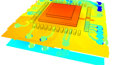
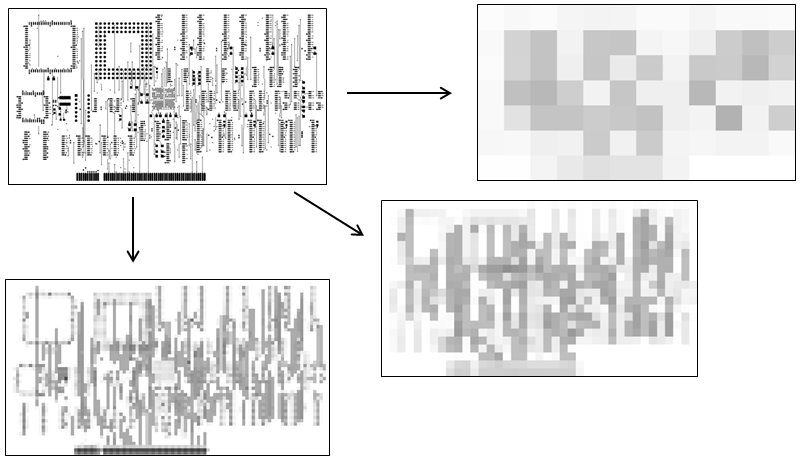 Direct interfaces (installed with FloTHERM) to Expedition, BoardStation and other EDA tools extract all the necessary information required for an efficient yet thermally accurate definition of the PCB/Substrate. The complexity of modern day PCB designs, as is evident from the winners of Mentor’s annual Technology Leadership Awards, is such that it is intractable to extract the EDA data as 3D at source. Instead we have pioneered a ‘light’ approach whereby all metallic routing/via information on conducting and dielectric layers is rendered to a high resolution raster image. When further compressed, the data is a fraction of the size it would otherwise be, without losing any of the fidelity required to reconstitute a detailed thermal representation. To do that, a real-time graphics processing technology is used in FloTHERM to convert the images to a thermal conductivity map. The resolution is slider-bar controlled, allowing an appropriate detail to be achieved. For forced convection applications, where most of the heat does not go into the PCB, a lower resolution can be used. For natural convection or conduction cooled environments a much higher resolution can be used that accurately resolves the patch-by-patch orthotropic conductivity thermal resistances on each PCB layer.
[As an aside, here’s an interesting whitepaper on 10 tips for streamlining PCB thermal design]
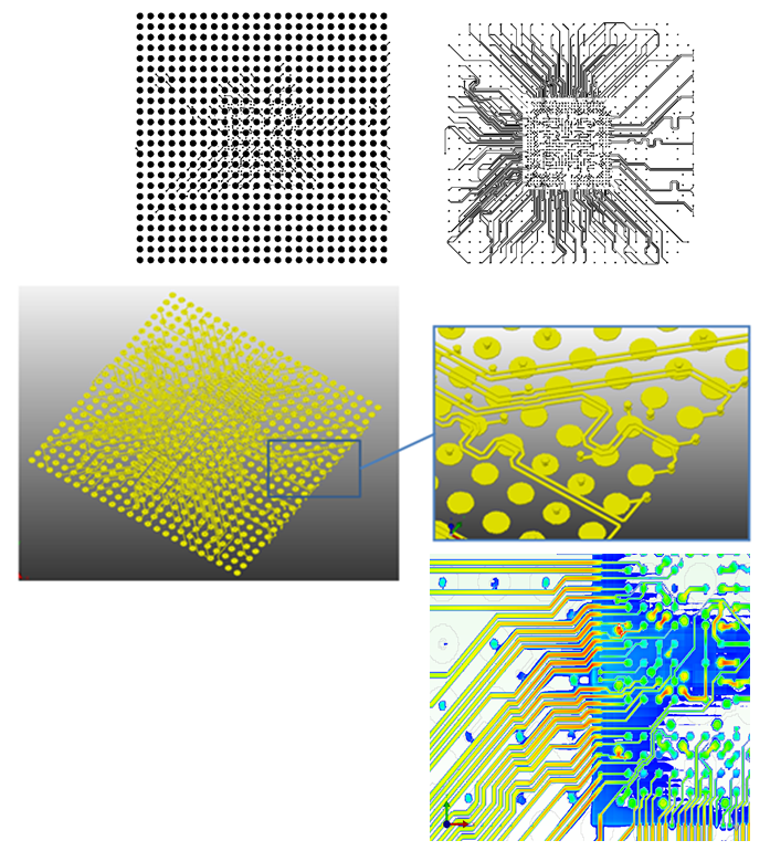
An alternative technology can also be used to convert any image (regardless of source) representing a metallic distribution into an extruded identical 3D representation. Here no orthotropic pixelated patches are created, a single object with an assigned material can be created that is the 3D (extruded) equivalent of the 2D image.
Just by obtaining some images of the Cu distribution in a BGA substrate a 3D model may be constructed and thermally simulated.
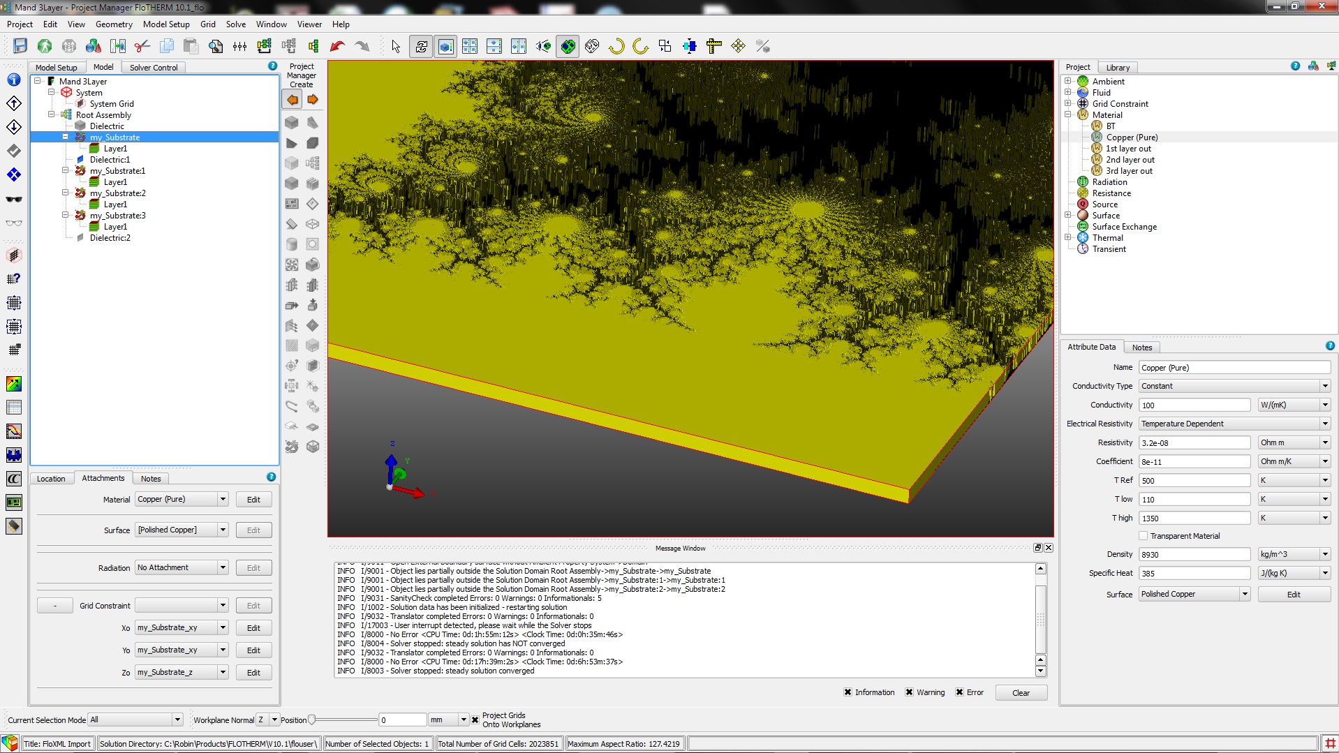 I’m a big fan of fractals. So, to exercise this functionality further I converted a picture of a part of the Mandelbrot set into a 3D extruded solid, made it out of Copper, embedded in a lower conductivity substrate and imposed a 100degC temperature difference across it and simulated the resulting heat flow. I’ve yet to figure out a useful application for this but hey, it looks all kinds of stunning.

Not content to stop there (OK, I got carried away) I also simulated the hot spur of a well known footballing chicken (COYS!!)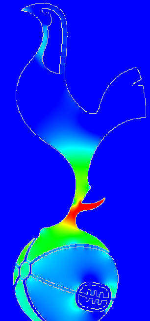
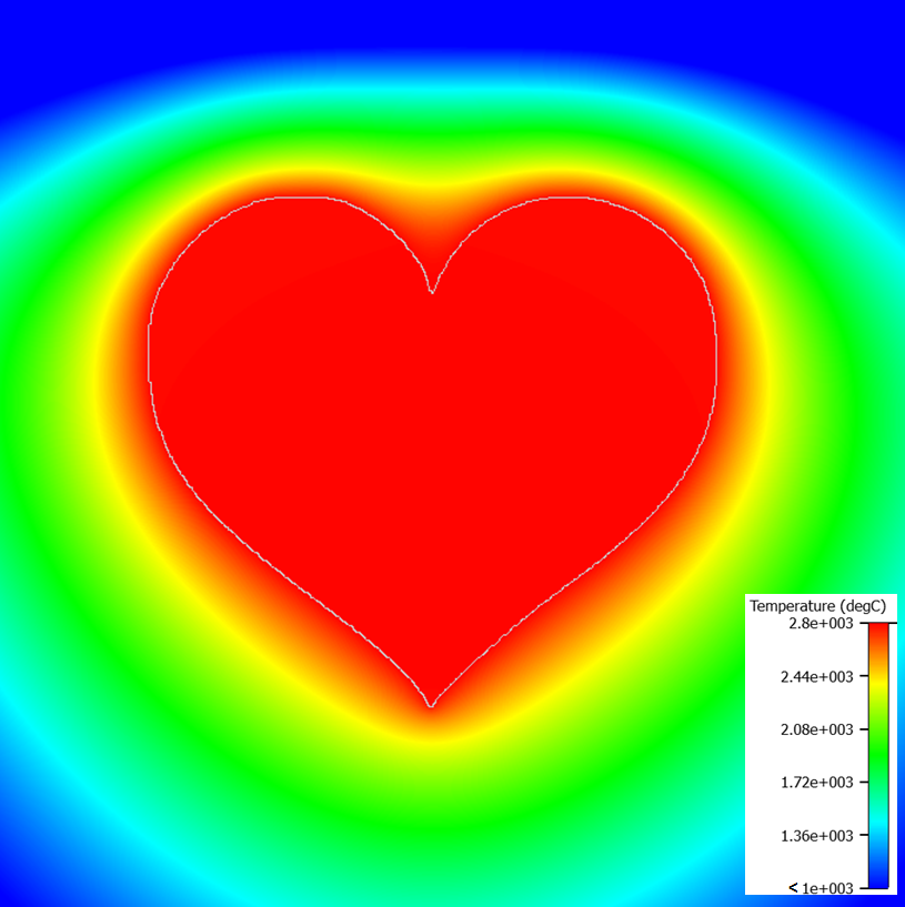
And finally, as Valentine’s day approaches, and as is representative of the love I have both for my wife and for this functionality, the thermal behaviour of a dissipating heart (6W, k=385W/mK embedded in a 2W/mK substrate, peripheral HTCs of 1000W/m2K (top) and 100W/m2K (other sides) @0degC), based simply on an image ![]() was also simulated in FloTHERM.
was also simulated in FloTHERM.


Happy Valentine’s day everyone. May your day be filled with love 🙂
10th February 2015, Ross-on-Wye