What! All that just for that? The bonkers world of CPU cooling.
My colleague Ed and I were marvelling the other day at the CPU cooling unit from one of our training desktop PCs undergoing a repair. “What, all that just for that!?”. The CPU itself was but a small square wafer compared to the behemoth that was the ducted fan and heatsink with integral heatpipes mounted on top of it. Whereas transistor sizes are measured in nanometres cooling systems can be weighed in pounds. However it’s not the weight of the cooling system that cools the chip, it’s the surface area. That and a good fast flowing cool air stream. Modern day CPU (and GPU) cooling systems aren’t just dreamt up and put directly into production. Much care and design attention is spent on them. For FloTHERM this is a bread and butter application, no wonder it is used used by so many PC OEMs and their suppliers.
With Core i7s now pushing 130W TDP with a die size of 0.33 in^2 the die power density is up at 390 W/in^2. The surface of the sun is at 40 kW/in^2. A few more years of Moore and thermal engineers will be tasked with cooling packaged slithers of sun power. In the mean time there appears to be a gravitation towards mirroring automotive design.
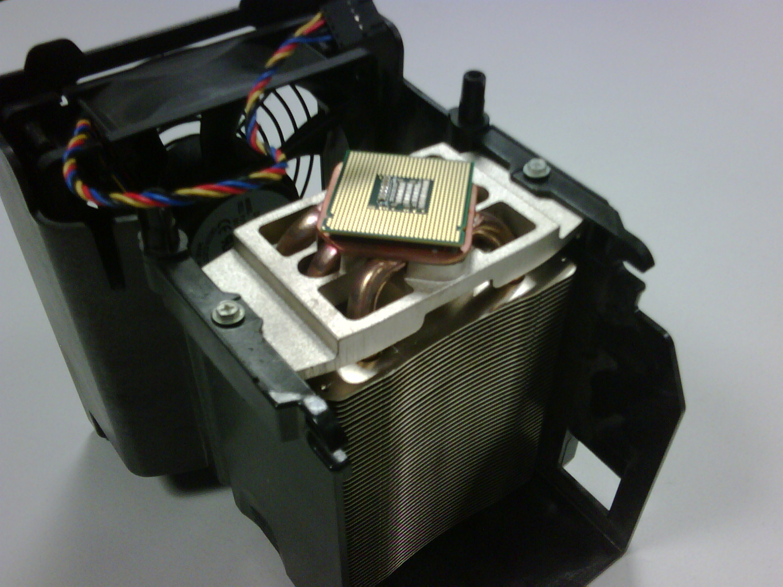
 The use of a forced convection cooled radiator system in cars is uncannily like the heatpipe/heatsink system seen here. Whereas piped liquid is used as the medium to convectively transfer heat from it’s source inside the engine block to the radiator, heatpipes use a little bit of liquid and a closed evaporation/condensation cycle to take heat from under the CPU down to all the fins that are being constantly washed over by nice cool air. Kind of a conductive heat loss manifold akin to exhaust manifolds coming out of an engine.
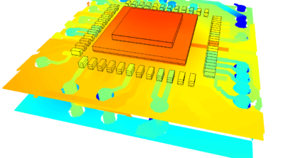
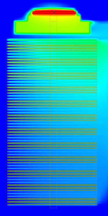
 Easy enough to model in FloTHERM. Sure, you can simulate the effective thermal resistance of the heatsink, verify whether it matches what you had assumed in your initial temperature rise calculations. Observation isn’t really design though. Making something better is.
For this application one could investigate what effect the number, thickness and pitch of the heatsink fins would have on the thermal performance. A design of experiments followed by a response surface optimisation will allow you to investigate in real time the relationship between these design parameters and their thermal effects.
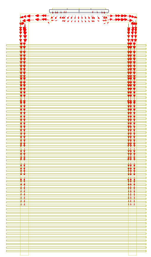
Alternatively, looking at the ‘ShortCut number‘ in the air between the heatsink fins will give an indication of the effectiveness of local heat transfer, where are the fins not working effectively, where can I shave off some metal, save weight, save cost, decrease pressure drop?
6 heatpipes take the heat from the CPU down through to the fins. What is the best configuration of the heatpipes? Equispaced or biased towards the centre of the fins? Are 6 needed or, with some optimised locating, can you get away with 5 or even 4?
CFD -> Conceptualising a Finished Design
17th November 2011, Ross-on-Wye