Layout automation using advanced PCB design techniques – Part 3
In part 2 of this blog series we covered the most important step in using routing automation, creating proper design rules. In part 3 we will continue with the design process by looking at routing automation and length matching.
First and foremost, the simplest form of routing automation is fanning-out pins from SMD devices. This is the process of using auto-routing technology to route short traces to a via so a net has access to internal layers. To take full advantage of automated fan-out design, rules are required. Item’s like, fan-out direction from SMD devices/pins, trace width to be used by net or class (i.e. – power and grounds nets usually require large traces), via type to be used by net or net class, allowed length of trace, and clearances.
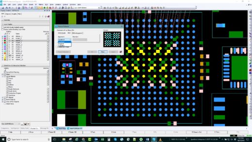
Let’s start with BGA’s, these devices for the most part are the simplest, choose 1 of 3 options and go, Figure 1. For non-BGA parts you have more choices. For example, a high pin count connector like in Figure 2. We would like the power and ground pins routed to the outside and all the diff pair pins to be routed on the inside to minimize length discrepancies. To achieve this we’ll set the fan out
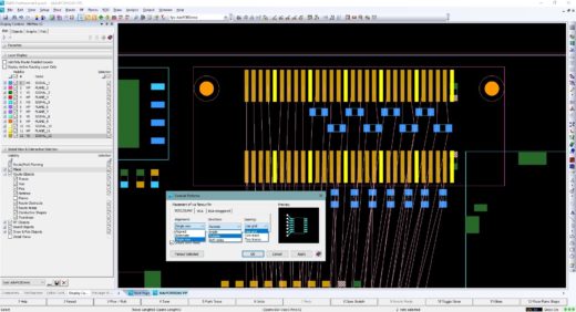
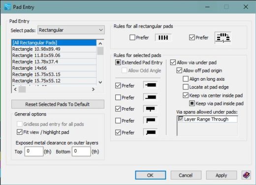
direction for outside, selecting the PG pins and perform the fanout. Next, adjust the fanout direction to inside, select the component, and fanout the remainder. For tight designs or BGA’s with fine pitch ball spacing placing vias in SMD pins of passives or even BGA pads is required. Being able to adjust settings on-the-fly and having finite control makes the process that much easier. In our case, we need to place decoupling caps directly under the BGA’s which requires vias to be placed in the pins. After defining via-in-pad from PADS Professional’s Editor Control > Pad Entry, we can simple start placing capacitors at the appropriate locations with no issues, See Figure 3.
Download a free trial of PADS Professional today!
Now that we’ve created the appropriate rules and placed our fanouts it’s time to start routing. This phase of the design usually takes the most amount of time especially when hand routing. Point and clicking each point with no push-and-shove. It’s surprising how many designers today still prefer to use this method regards when there tool contains interactive routing technology. If you’re a designer still using this old style routing method, you owe it to yourself to investigate the push-and-shove routing capability of your tool. With PADS Professional you have the best technology in the industry. Two options are available; interactive push-and-shove for single or multiple nets and Sketch routing. This technology provides 5X to 10X savings in design routing time. To see how it works and how much faster you can route watch the following webinar. Reduce Design Time Using Routing Automation
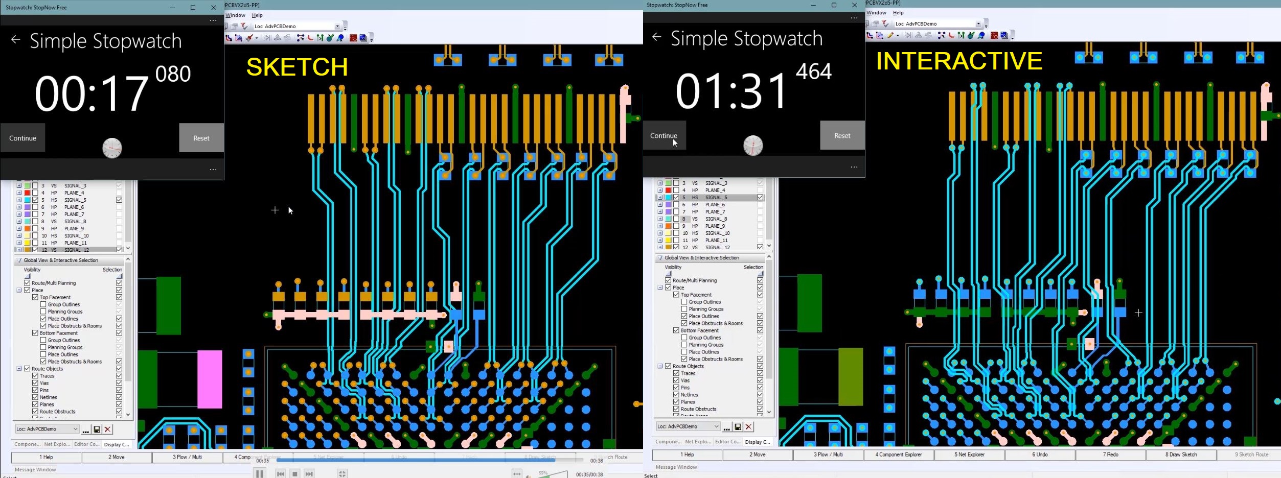
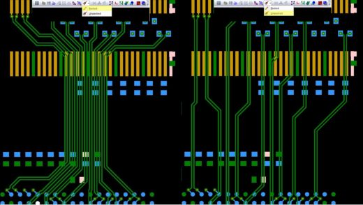
As an example, routing the same connector we fanned-out earlier. We used interactive routing, not point and click, and routed all the differential pairs from the bottom side of the connector. This process took about 91 seconds to complete. Using PADS Professionals sketch routing technology to route the same differential pairs only took 17 seconds, See Figure 4. Quick tip, there are a few options when using sketch routing. You can select an option to have all the routed nets packed together. This takes up less room and uses the minimum spacing for trace-to-trace. Alternatively, you can choose unpacked which will spread the traces and route each in the shortest distance possible. For our example I’ll choose unpacked to produce the best results See Figure 5.
So,what are the advantages of using Sketch routing? Simple, you can reduce your routing time by 50 to 90%, your guiding traces where you want the router to place them so the final results is the same or very close to how you would have hand routed them. And, it’s so fast you can experiment with rules, part placement, and different routing schemes.
Our next design task after routing is length matching nets if/as required. During our rule creation phase we created match rules for all nets on our example connector. The back half of the connector and the front half all need to be matched within 200 thousands. First we’ll work on a few nets using manual interactive tuning. To start manual tuning we select a segment where the serpentining will start. Right-click, tune routes, manual tune, See Figure 6. A box appears with the start of a serpentine inside. Using the drag handles we can add trace horizontally
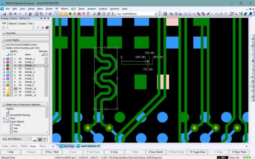
or vertical. To help determine when we’ve meet our rule, PADS Professional provides a tuning meter on the cursor. This gives us real-time feedback of our current length and where we are relative to the min and max values. If we need to modify a tune section already placed we can select the tune section and move or readjust as needed.
If your design requires a lot of traces to be tuned interactive routing can be a bit tedious. PADS Professional provides an option which allows you to perform multi-trace auto tuning. To complete our example with the connector we’ll use the auto-tuning option to complete all the differential pairs on the bottom half of the connector. Similar to using sketch routing we need to select those nets we want to tune, right-click choose Tune>Tune. If you want to view trace length values and verify all selected nets where tuned, right-click and choose Target Lengths. See Figure 7.
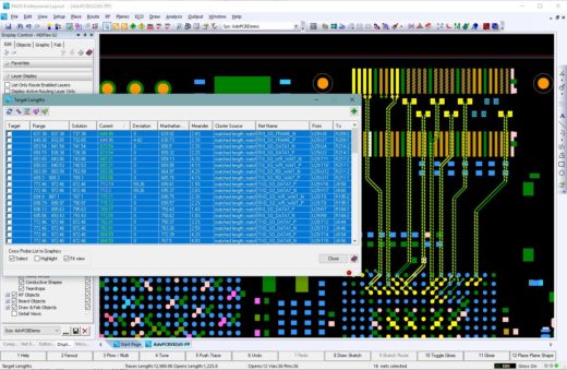
This will open a spreadsheet view with the selected nets highlighted providing length information and if matched with-in there limits. Additionally we can see the deviation from the minimum if under or maximum if over. For matched groups we can select a target length to which all others will match themselves to. Like with the manual tune function all the serpentine areas are objects so they can be selected and adjusted or moved if needed.
Check back soon for Part 4 of this blog series and thanks for reading!