Signal Integrity Design Fundamentals for Success: Episode 1
So, what, exactly, are differential impedance traces and how do they work?
I remember hearing a story from a former colleague about how their engineering team had spent nearly a month trying to solve a mysterious bit error rate (BER) issue on a seemingly well-designed and otherwise sound PCB. After many painstaking diagnostic hours, not to mention added resources and a looming release date, they finally found their answer. So what was it? I’ll get back to that.
With the ever-growing requirement for more densely populated PCBs, paired with the added complexity of high-speed signals in modern electronics, mitigating the effects of electromagnetic interference, noise, and crosstalk is crucial for proper circuit functionality. One commonly implemented design technique is the use of differential signals. To better understand the concept of differential signals, let’s first take a look at how single-ended traces behave. A single-ended trace is, well, just that: a single trace with one starting point, one ending point, and a common ground, carrying a signal from a source to a receiver. Unfortunately, when you start packing more and more traces at higher and higher speeds onto the same board, the potential for noise coupling on your sensitive traces gets greater and greater.
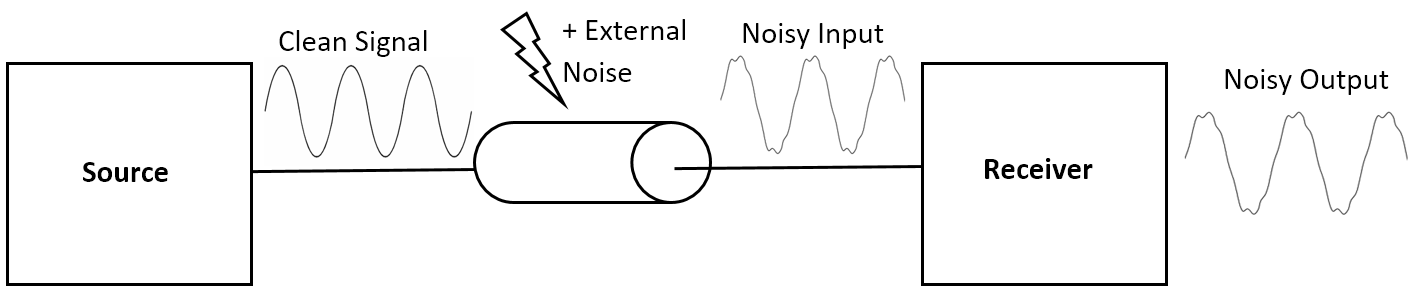
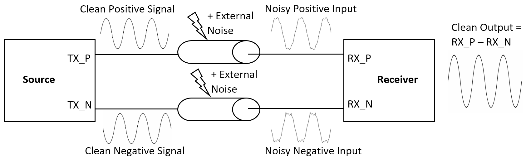
Noise from EMI can change digital logic levels to unrecognizable values, leading to potentially critical issues on data lines. Alternatively, when using differential signals, the receiving input measures the difference between TWO signals – one positive and one negative – instead of the difference between one signal and a reference voltage. By designing the two traces with nearly-identical symmetry, and then placing them very close together, EMI and other unwanted noise should be coupled equally on each trace. Because the same noise is present on both traces, when the difference is taken between the signals, the noise gets canceled out. Thus the output signal will remain consistent regardless of the presence of unwanted common mode noise.
Differential pairs sound great, so what could go wrong? In the design of differential impedance traces, very close attention to length, impedance, spacing, and via count/positions of the pairs is imperative for proper functionality. A mismatch in symmetry on the traces can mean unequal noise coupling and/or a time delay between each signal reaching the receiver, resulting in an inaccurate output signal.
This leads me back to the story of my former colleagues. Their BER problem was ultimately caused by a timing discrepancy on a pair of high-speed differential traces. To put it simply, the length of one trace was too long in relation to the other. This resulted in one signal arriving at the receiver before the other, and subsequently, an inaccurate “difference” between them. Once the trace lengths were properly redesigned, the BER dramatically improved, which then resulted in a successful product launch (albeit a little later than promised and a with few more grey hairs sprouting on the heads of the team members).
These types of signal integrity issues can be incredibly difficult and expensive, not to mention stressful, to retroactively diagnose, so the best solution is to always try and find them on the front end. One of the many rules included in HyperLynx DRC is the “Diff Pair” rule, which automatically checks for consistency in the length, spacing, and via count/positions of your differential pairs. By taking a couple of minutes to run this rule on your design, it is easy to recognize a potential symmetry flaw in your differential traces before your PCB is ever sent to the manufacturer, thereby saving a significant amount of time, money, and frustration later on. To learn more about HyperLynx DRC and how it can help with your PCB design process, check out my on demand webinar: Automated Rule Checking for Faster Time to Market
Download a free trial of PADS Professional today!


Comments
Leave a Reply
You must be logged in to post a comment.
Hi Rebecca,
Thank you for this very clear approach to signal integrity design.
Regards,
Eric