The Necessity and Benefits of MCAD Collaboration – Part 1
In this two-part blog series, we’ll examine the necessity and benefits of ECAD/MCAD collaboration. This first blog describes the need for electrical and mechanic designers to seamlessly share digital information with each other to ensure first pass success of complex electro-mechanical systems.
Today, designing printed circuit boards in 3D is not the exception, it is the norm. Printed circuit board design is not done in a vacuum, it is just one aspect of product design. Designing mechanical enclosures alongside the printed circuit boards and incorporating the mechanical piece parts for the enclosure, brackets, and the heat sinks collaboratively is now being done within the design environment. Essentially, a digital model of the end product is created within the CAD environment.
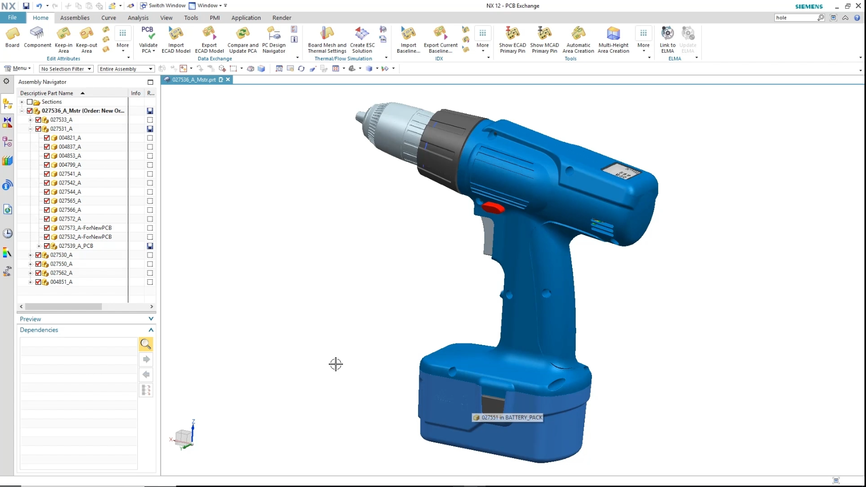
A 3D Mechanical Model Created in NX
Poor, or lack of, electromechanical co-design processes account for projects missing their time to market and cost targets by 50% or more. Ignoring the necessity of electro and mechanical collaboration throughout the product design flow results in time spent fixing costly mistakes, re-spinning PCB designs, and missing critical time to market schedules. This blog will demonstrate how modern ECAD/MCAD collaboration works and how it can be used to overcome the challenges of electrical and mechanical co-design and get it right the first time.
Antiquated ways of moving data between ECAD and MCAD should be avoided. The digital information that is available in the CAD tools should be used to make the moving of data between the tools faster, easier and more accurate. This allows the electrical engineer to take advantage of the work that the mechanical engineer has already done in his tool to design the board outline, place critical components and mounting hole locations. That data can be brought directly into the PCB design tool with a couple clicks of a button.
ECAD/MCAD Collaboration:
PADS Professional provides powerful ECAD/MCAD collaboration functionality that is easy to use and saves significant time. It allows the mechanical engineer and the electrical engineer to work in their familiar authoring tools, while also allowing the easy sharing of data between those tool environments. Though the images used in this blog are with NX from Siemens for the MCAD tool, PADS Professional MCAD collaboration will work with any MCAD tool that supports the industry standard IDX interface.
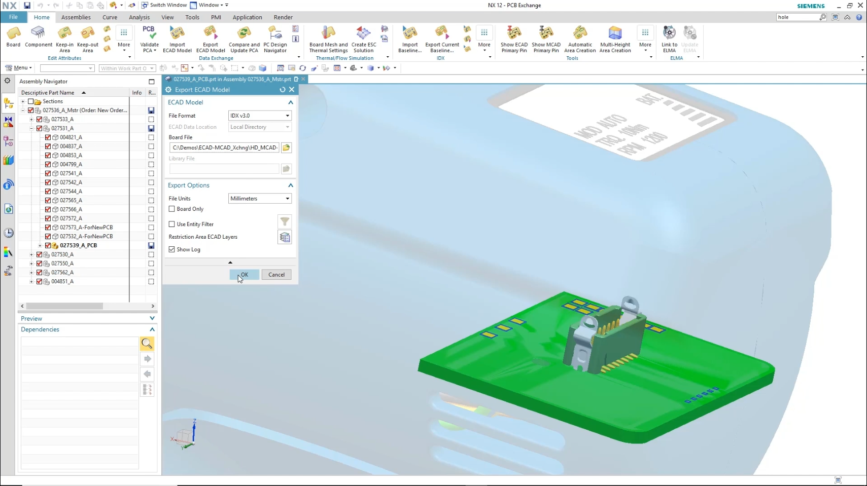
The mechanical engineer starts the design by creating the board outline, inserting mounting holes and placing critical components, such as connectors, heat sinks and other large mechanical structures. In parallel with this initial mechanical design work, the electrical engineer is working on the schematic. When the electrical engineer is ready to start placing components, he opens the 3D environment in PADS Professional and activates the MCAD collaboration feature. The collaboration baseline file provided by the mechanical engineer is selected and all the work done by the mechanical engineer is seamlessly imported into PADS Professional.
 PCB baseline Created in NX
The electrical engineer can now begin placing components. This can be done in the familiar 2D environment using the component explorer window available in PADS Professional. Rooms of components that were grouped together in the schematic can be dragged, en masse, onto the PCB. Individual components can then be pull out of the groups and placed in the desired locations.
Opening a 3D tab inside of PADS Professional will show the board in full 3D. Components that were used in previous designs will already have 3D models assigned to them. This will also reveal any new components that are lacking 3D models. 3D models for these devices are assigned by selecting each device and clicking on Import Model on the 3d toolbar of PADS Professional. Step models may be downloaded from a vendor’s web site and are also available from numerous free content providers. Once the 3D models are imported, these devices can be stored for use in future designs using the Update Library button on the 3D toolbar. In addition to STEP models for all electrical components, the mechanical engineer provides STEP models, created within his MCAD environment, for all mechanical components and piece parts like screws, stand-offs, brackets and heatsinks.
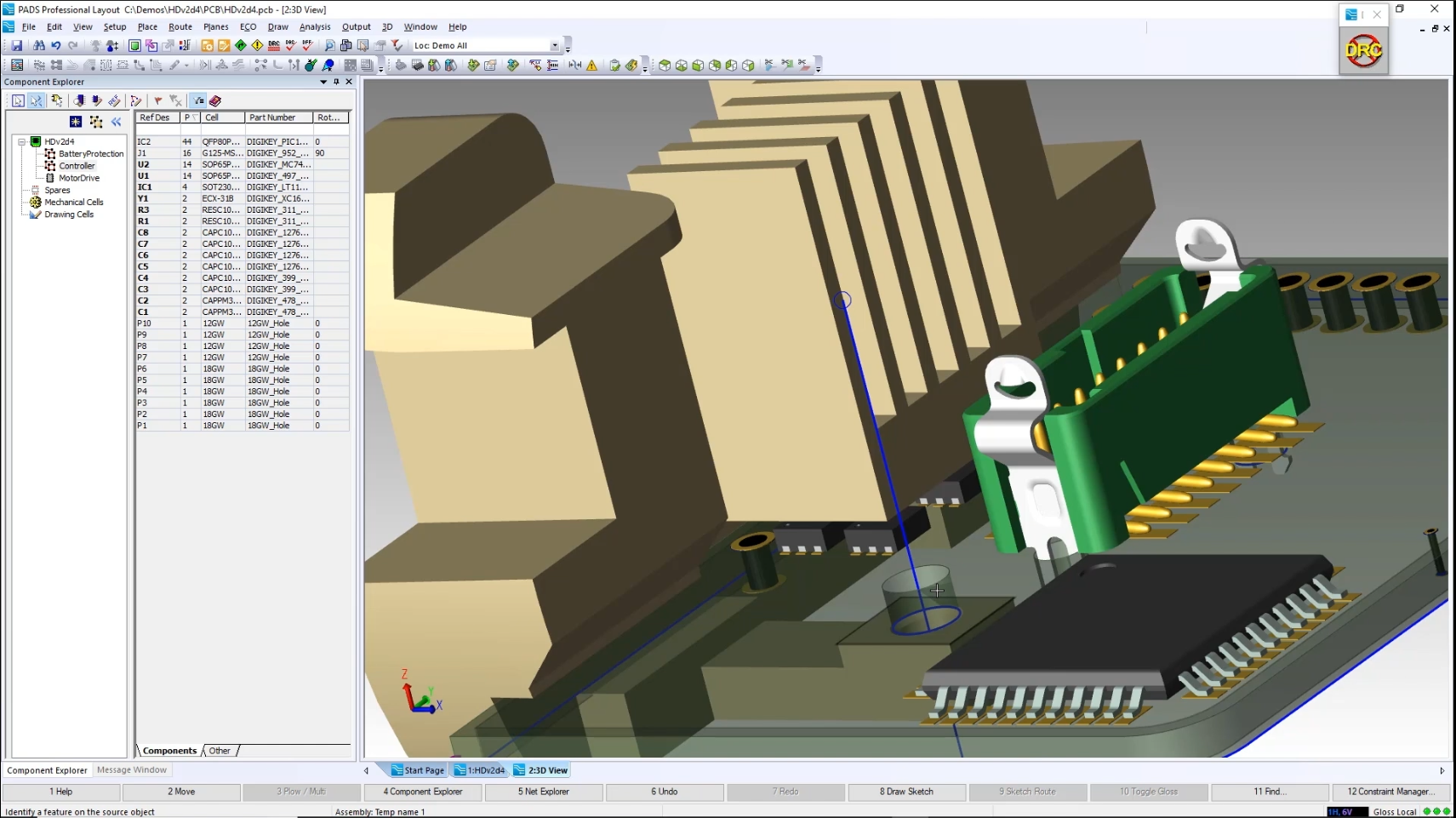
3D View of Populated PCB in PADS Professional
Watch what we’ve talked about in action!
View the archived webinar.