Automated Electrical Design Rule Checking for Faster Time to Market – Part 2
In part one of this 2-part blog series, we examined how electrical Design Rule Checking (DRCs) uncovers violations that often go undetected, leading to higher quality designs on aggressive schedules. This second blog looks at more advanced capabilities in HyperLynx DRC in PADS Professional, including analyzing signal transitions, timing on high-speed nets and signal and power integrity. To read part one, click here.
Analyzing Signal Transitions from Layer-to-Layer
The ‘vertical reference plane change’ rule looks at instances of signal transitioning from one layer to another. While changing planes is a common design practice to accommodate today’s densely-packed PCB layouts, care must be taken to reduce risk of common mode radiation. Frequently, capacitors or stitching vias are placed to allow for continuous current return path. This rule determines whether those conditions are met. The designer runs the rule on their previously defined GPIO object list to specify constraints for plane changes. If there are violations, further exploration could show that they occur on different pins of the device header. The need for addressing those violations would depend on what the headers are used for and the purpose of those pins.
Timing on High Speed Nets
The next rule that the designer runs is the ‘delay and links matching’ rule. Timing on high-speed nets is incredibly important for proper functionality, especially on DDR nets. If DDR signals do not reach their destination with proper timing constraints, the memory will not work properly. Timing issues occur for a multitude of reasons including transmission line propagation delay due to layer stack up, dielectric properties and trace routing. As delay issues are often due to unique physical properties of a PCB, it is an important parameter the designer must take into account. As DDR nets often fall victim to delay issues, the designer creates another object’s list containing the DDR nets.
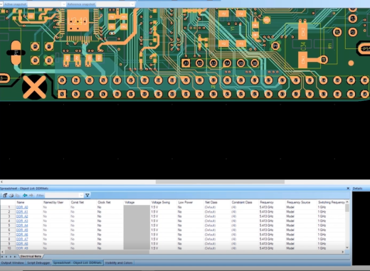
For this specific test, the designer checks the delay matching, the length matching, or both. One of the powerful features of HyperLynx DRC is automatically calculating necessary values from the layer stack up information. The designer specifies a new created DDR net object list as the target for this rule. In the customizable parameters, the designer can request the DRC tool to calculate the propagation delay from the stack up, by selecting ‘Yes’ for the parameter. The designer then executes the rule with the custom settings. If there are violations, PADS Professional will display the exact affected nets highlighted in red, and the reference net highlighted in green.
Signal and Power Integrity:
HyperLynx DRC has advanced rules that aid in identifying possible signal and power integrity issues. In DDR Design that uses fly-by topology, stub length is important for proper functionality.
- The ‘Fly-by Topology’ rule checks that nets with fly-by topology are designed with proper constraints. One area of focus is on crosstalk coupling because it causes serious timing and functionality errors and is very difficult to manually diagnose on a manufactured PCB. The fly-by topology rule helps the designer to identify unwanted crosstalk on sensitive nets.
- The ‘Signal Supply’ rule checks for discontinuities between an integrated component supply planes and its connected traces reference plane. These types of violations can lead to potentially strong radiation and result in EMI failures.
- The ‘Power Ground Width’ rule checks for narrow trace widths on power ground nets. If the power and ground traces are not designed wide enough, the resulting current on that net can be insufficient. This potentially leads to a host of problems that include inadequate power supply to components, as well as unnecessary heat production.
- The ‘Filter Placement’ rule checks for the presence of filters within close proximity to connectors pins. Filters are necessary to suppress noise that may be present on a connector to protect sensitive signals and prevent radiation. The absence or misplacement of filters on connectors can lead to serious EMI issues and failures.
- The ‘Return Path’ rule ensures that the tested signals have a sufficiently low impedance return path. Adhering to proper return path rules is important, especially with the increase in today’s high speed circuit design requirements as well as the decrease in PCB size. In the event of the return current on a trace not flowing properly underneath the conductor, it could take an unintended path through other areas of the designer’s circuit, possibly resulting in EMI issues.
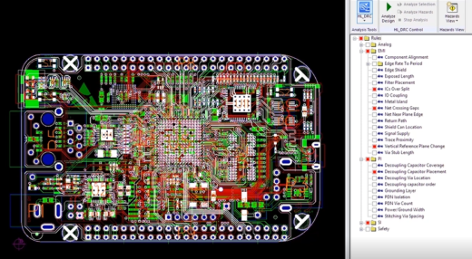
In PADS Professional, the designer can view all the rules that were run in the Analysis Control window. The specific violations are described in greater detail in the Hazards window. If the designer decides to ignore a hazard, they can accept the hazard by choosing the checkmark on top of the Hazard Explorer. The designer also has the option to write comments on accepted hazards to easily keep track of design decisions. The designer can then report all violations in a text file by clicking on the ‘Report all Hazards’ icon. This creates a list view of each violation sorted by hazard type. The designer can also choose to export a text file list of only the accepted hazards that includes all comments on accepted hazards.
HyperLynx DRC for First Pass Success:
With PADS Professional and HyperLynx DRC, the designer ensures that their design will work on the first pass by finding difficult to diagnose errors such as:
- Improper termination on sufficiently long nets
- Inadequate spacing between adjacent traces
- Poor connection between traces and component pins
- Decoupling capacitors placed out of order
- Via stub lengths that cause resonant frequency knowles
- Inadequate stitching via placement on guard traces
- And more…
PCB layouts are verified from component placement to nets crossing splits, proper grounding of pins to trace topology, and everything in between. With PADS Professional and HyperLynx DRC, the designer ensures that their design will function properly without wasting time and resources on costly board failures and design re-spins. Ensuring that your PCBs meet all advanced electrical rule expectations on the front end for first pass success.
To learn more about the features and capabilities described in this blog series, check out the routing automation webinar available On-Demand!
Thanks, Rebecca