Automated Electrical Design Rule Checking for Faster Time to Market – Part 1
In this two-part blog series, we’ll examine how electrical Design Rule Checking (DRC) uncovers often-undetected violations, leading to higher quality designs on aggressive schedules. This first blog looks at some of the many capabilities in HyperLynx DRC in PADS Professional, starting with basic rule checking, such as differential pair symmetry and decoupling capacitor placement.
Did you know that when PCB designs undergo fabrication re-spins, the average cost is nearly $28,000 per re-spin? PADS Professional offers unique electrical DRC (Design Rule Check) capabilities to help ensure that PCB designs meet their performance, time-to-market and cost goals by reducing or eliminating potential re-spins. These advanced checks will alert users to a multitude of physical violations that can be easily overlooked during manual inspection. More than 70 built-in, customizable Analog, Signal Integrity (SI), Power Integrity (PI), Electromagnetic Interference (EMI), and Safety checks allow designers to identify and correct issues, reduce error-prone manual inspection, and eliminate costly design re-spins that can impact the product’s time to market.
To illustrate the power of HyperLynx DRC in PADS Professional, this article will use the open source BeagleBone Black design as an example. The BeagleBone Black is a low-cost, low-power, single board computer produced by Texas Instruments, which is commonly used amongst developers and hobby enthusiasts alike. It consists of a TI Sitara processor, 512 MB DDR3 RAM, and 2GB of flash, in addition to a number of physical interfaces and other features.

Getting started with HyperLynx DRC in the PADS Professional suite:
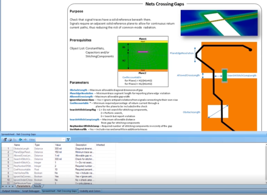
With the increased complexity and density of today’s PCB designs, finding and reviewing all instances of a net crossing a split plane can be a grueling manual process. Standard simulation tools do not typically check for the presence of nets crossing splits, but HyperLynx DRC quickly pinpoints when and where these violations occur. When a high speed net crosses a split plane, it can create an impedance discontinuity on the signal trace, possibly leading to unwanted reflections, radiations and crosstalk.
Once the PCB design is loaded into DRC using the integrated Analysis Control feature within PADS Professional Layout, the designer creates a custom object list for only the GPIO nets. Creating separate object lists allows users to run rules on only specified nets, eliminating unnecessary violations. In this example, the GPIO signals are likely to fall victim to the negative effects of an impedance discontinuity, so they will be the focus of the Nets Crossing Gaps simulation. Each rule within HyperLynx DRC has a built-in description, along with physical prerequisites and any available customizable parameters.
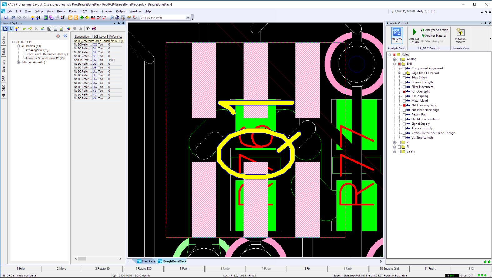
After running the Nets Crossing Gaps rule on the GPIO nets, several violations appear. In the DRC spreadsheet tab, each instance of the violation is listed. By clicking on a single instance, the location of the error on the design is highlighted, allowing the designer to review the issue and gather more information. The violation data from the DRC client is also automatically available within PADS Professional Layout. This feature allows the designer to make the necessary changes to their layout without having to manually cross reference between tools. Once the violation has been fixed in the design, the rule can be re-run directly from the Analysis Control feature within the PADS Professional Layout window to ensure that the proper changes were made.
In addition to re-running the Nets Crossing Gaps rule, the designer chooses to run the IC Over Splits rule from within the Analysis Control window. The IC Over Splits rule will check whether Integrated Circuit (IC) components have a proper reference beneath them. If an IC does not have an integrated reference plane in its package, and is not properly referenced beneath on the board, common mode radiation may occur. A number of instances of ICs without designated reference planes are found in this design. To further review where the errors occur, the designer can select a specific violation and the tool will jump to that location on the design.
Differential Impedance Rule:
The BeagleBone Black design has a couple of differential pairs with a 90 ohm differential impedance value. The designer has set up a constraint class using the Constraint Manager in PADS Professional Layout to specify and define these nets. The constraint class’s net assignments are automatically loaded into HyperLynx DRC from the constraint class definitions in PADS Professional. This makes it easy for the designer to quickly create a DRC object list to contain the nets from the constraint class. By running the Differential Impedance rule on this object list, the designer can verify that the differential impedance is consistently 90 ohms on all segments of the included traces. In the customizable parameters for the rule, the default target impedance value is 100 ohms, and thus should be changed to 90 ohms for this specific case. This rule passes without any violations, indicating that there are no problems with the impedance on these differential traces.

Decoupling capacitor placement
One of the many challenges that engineers must deal with is ensuring that the defined parameter requirements for each component are being met. With HyperLynx DRC, component requirements can be added to the tool to automate the verification process. The TI processor’s data sheet specifies that the maximum allowable distance for bypass capacitors from the component on the VDDS DDR nets is 400 mils. If decoupling capacitors are not placed properly, there is a high chance that the DDR3 interface could malfunction. The Decoupling Capacitor Placement rule determines whether decoupling capacitors are placed within defined parameters around the IC. The designer specifies the 400 mil radius, which was found in the data sheet, and runs the rule on the VDDS_DDR nets. The results show a number of violations where decoupling capacitors are not present within the required radius.
Check back soon for part 2 of this series on Electrical Design Rule Checks.
To learn more about the features and capabilities described in this blog series, check out this DRC webinar available On-Demand!
Thanks, Rebecca


