Reduce Design Time Using Routing Automation – Part 2
In part two of this 2-part blog series on intelligent routing, we examine more advanced routing automation such as sketch routing for differential pairs, interactive trace tuning and dynamic and ground planes for large spacing. To read part one, click here.
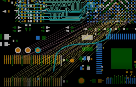
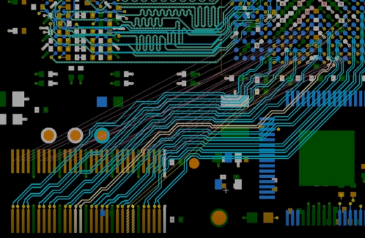
Sketch Routing for Differential Pairs
Sketch routing is extremely powerful for routing differential pairs. The first step is selecting a set of nets and choosing a layer on which to route them. Based on the design rules set up earlier, the tool suggests the optimal route for the differential pairs. Here again, the designer can quickly examine multiple different routing approaches in a matter of minutes. Any individual net that is not in an optimal routing position can be quickly identified and addressed.
In certain situations, the designer may not want to use the automated sketch router but instead will want to rely on interactive routing for a single trace or differential pair, or even for a group of nets. The unique dynamic ‘push and shove’ route technology in PADS Professional enables the designer to move vias and nets around and make adjustments on the fly. Based on the designer’s preference, the tool will allow the designer to see the traces and prompt them to stop at any time to make adjustments, guiding the designer until they are satisfied with the routing.
Interactive Trace Tuning for DDR
Routing high-speed DDR (double data rate) nets requires a specialized set of capabilities. The designer can tune the nets to very specific lengths to meet the DDR requirements using the interactive or manual tuning capability within PADS Professional. An advantage of this function is that the tuning is like an object which, when clicked on, displays a tuning box, allowing the designer to adjust it on the fly.
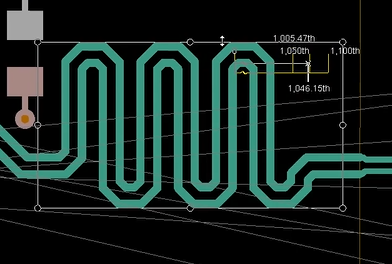
The designer first selects where the tuning should start and brings up a tuning box around those particular nets. The designer then can zoom in visually to expand the tunes and use a gauge on the cursor to see if the nets meet the length requirements. The designer can then drag the net until it meets the length requirement. The viewer assists the designer by turning the net yellow, green or red to indicate if the desired length is near, achieved or exceeded. During the tuning process, the tool will push and shove vias and objects around as applicable to accommodate the tuned nets. If the designer wants certain objects to not be pushed, they can select and lock those items. Once the desired nets are tuned and meet the length requirements, they can be fixed and locked down so that they are not adjusted by other routing or modifications on the PCB.
What if the engineer makes a late stage change and wants larger spacing between the nets? Instead of having to tediously reroute all the traces over again, using PADS Professional the designer simply changes the design rule to the larger value. Then the DRC visualizer displays any violations on the board due to the change. It will cross hatch the traces to indicate the exact areas of violations. The designer can then select the affected nets and select the repair function. Within seconds, the auto-routing algorithm re-spaces the nets. This saves the designer considerable time when dealing with inevitable design changes.
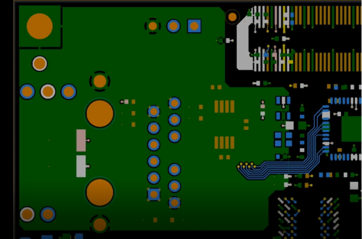
Dynamic and Ground Planes for Larger Spacing
Once all the nets have been routed, we’ll focus on putting in the power and ground connections. Although it is not considered a part of routing automation, it is indeed essential to route the power and ground nets and or put planes in the PCB. With PADS Professional, the designer does not need to draw shapes on the board if the entire layer is considered as a single net for power or ground. Instead, the designer creates what is called a route border. The tool will automatically create DRC violations if the designer goes outside of the plane area. There is no need to draw shapes on the plane layers as the tool automatically does this.
To save time, the designer can set the planes to dynamic, so that the entire area within the boundary is filled instantaneously. Anytime the designer places an object on that layer, voids are automatically added. It even helps the designer see how vias impact the current carrying capability of the plane. The designer can quickly move the vias around and see how the plane adjusts.
This is a huge benefit for RF designs or for high-speed, controlled impedance nets where the designer adds top, bottom and internal layers attached with stitching vias to reduce ground currents. Within seconds, the designer can determine the shape of the planes, set up parameters and fill in the plane with stitching vias. If not satisfied, the designer can simply undo the routing, change the parameter and adjust until they achieve the desired stitching via configuration.
Conclusion: Interactive Routing vs Sketch Routing
PADS Professional offers a wealth of routing automation capabilities that enable designers to create PCB boards faster with better results. These include
- Automated fanout for vias,
- Interactive single and multi-trace routing
- Automatically creating differential pairs
- Interactive tuning for DDR nets
- Dynamic plane functionality
- Via stitching for large plane areas.
Most importantly, PADS Professional offers an intelligent mix of interactive and automated routing capabilities—both that are far superior to traditional routing tools. Interactive routing is much faster than the usual ‘point and click’ manual routing. However, sketch routing can achieve the same results even faster. Most importantly, sketch router technology routes a majority of the traces and allows the designer to meet today’s tight design schedules and handle last minute changes quickly and easily.
To learn more about the features and capabilities described in this blog series, check out the routing automation webinar available On-Demand!
Thanks, Brent