Is Your PCB Layout Correct by Design? Differential Phase Matching Could Be the Answer.
One of the most important benefits of HyperLynx DRC is its ability to look for niche SI-related problems that other tools can’t. The differential phase matching rule is a good example of exactly that.
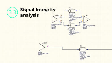
We know that differential pairs carry a differential signal. Which means they need to be 180 degrees out of phase at any given time at any given location on the board. If this does not happen, then the differential signal starts creating common-mode power which affects the signal quality at the receiver.
It is, therefore, important to keep the differential pairs the same length. Unfortunately, it’s unrealistic to expect the trace length to stay the same because of various physical objects on the board such as vias, turns and curves in the traces.
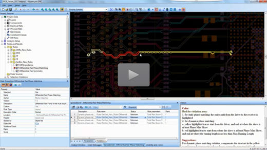
With HyperLynx DRC you can check that the differential pairs are statically and dynamically phase matched. When we check for statically matched, HyperLynx DRC checks for the length skew at all the trace segments. For dynamic phase matching, HyperLynx checks the maximum running length of the trace. If the trace length is found to be out of skew, it must be compensated by the next trace segment.
By catching design issues like not having phase-matched, differential pairs, HyperLynx DRC ensures that your layout is correct by design and reduces time to market. To learn more about how to use this rule, check out this video and try it out on your own designs by downloading the free edition!