SerDes Design Part 4: Frequency Domain Analysis for High Data Rate SerDes Links
Despite the fact that eye diagrams were a very popular compliance method for serial links, the traditional simulation methods used to obtain them required a high level of signal integrity (SI) and modeling expertise. In addition, the simulation runtime needed to obtain very-low bit error rate (BER) levels was significantly long. Channel simulations also needed to be repeated multiple times using various allowed settings for TX feed-forward equalizer (FFE), Rx continuous-time linear equalizer (CTLE), and decision feedback equalizer (DFE) settings.
Consequently, in the mid-2000s, industry interest shifted towards a simpler and quicker way of channel characterization consisting of a pre-defined set of frequency-domain channel parameters and associated limits.
IEEE 802.3ap – Annex 69B
Annex 69B of the IEEE 802.3 specification provides informative channel requirements for four Ethernet protocols, including 10GBASE-KR and 40GBASE-KR4. Those requirements include five frequency-domain channel performance parameters:
- Insertion loss (IL)
- Fitted attenuation of IL (ATT)
- Insertion loss deviation (ILD)
- Return loss (RL)
- Crosstalk
- Power sum differential near-end crosstalk (PSNEXT)
- Power sum differential far-end crosstalk (PSFEXT)
- Power sum differential crosstalk (PSXT)
- IL to crosstalk ratio (ICR)
Along with those parameters, the specification defines high confidence regions where, if the passive performance figures meet or exceed the masks, the channel is likely to operate at the required BER. Examples of Touchstone Viewer frequency-domain plots used for 10GBASE-KR4 channel characterization are shown in Figure 1.
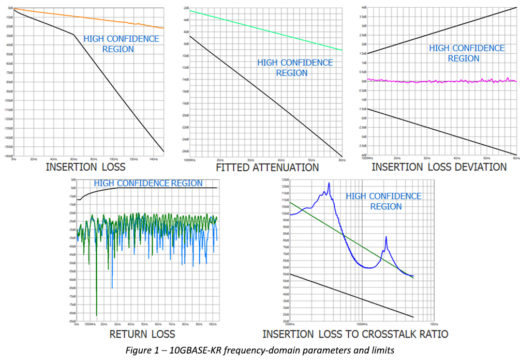
Insertion loss
Insertion loss is one of the most important metrics that is obtained from channels’ s-parameters. It describes how well the signal propagates through the interconnect. As a measure of signal attenuation, IL is affected mainly by the printed circuit board (PCB) material properties, trace length, and impedance mismatches. IL is expressed in dB and is one of the dominant factors affecting the BER of the link.
If a channel contains multiple impedance mismatches, multiple reflections will create ripples in the IL plots. Some peaks of those ripples might fail the IL mask, but the link might still operate at the targeted BER. To overcome this limitation, the IEEE 802.3ap specification introduced the fitted attenuation metric which is an approximation of the attenuation of the link. The curve fitting of the insertion loss can be done using various methods, such as moving average smoothing. Some reflective channels might marginally fail the insertion loss limit but they might pass the fitted attenuation limit.
Insertion loss deviation
The ILD metric is defined as the difference between the channel IL and ATT. ILD correlates to the channel impulse response ripple and is an important performance parameter for links with large numbers of reflections. Controlling ILD is important especially for short channels with low attenuation that are not capable of dampening the reflections. ILD is affected by the value of the terminations at the Tx and Rx ends.
While IL is a measure of the energy lost due to attenuation, the RL is responsible for most of the signal distortion. RL represents the amount of signal energy lost due to impedance mismatches in the link. The lower the value, the fewer reflections and, consequently, the lower the noise caused by reflections.
Crosstalk
Crosstalk is one of the most important channel characterization parameter and is the design problem responsible for most systems’ failures. Crosstalk is a measure of the unwanted signals that couple between various components of the channel and can be measured in both the time and frequency domains. In a link containing multiple lanes, as shown in Figure 2, the aggressors driving in the same direction as the victim have a far-end contribution, while the N aggressors driving in the opposite direction have a near-end contribution.
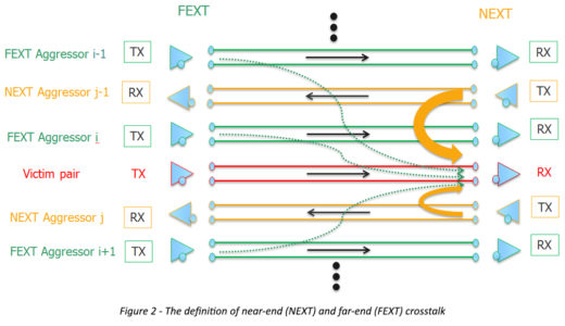
PSNEXT and PSFEXT are calculated as the power sum of the individual NEXT and respective FEXT aggressors. PXST represents the total crosstalk arriving at the receiver and is calculated as the power sum of the individual NEXT and FEXT aggressors. The IEEE 802.3 specification does not define crosstalk limits, recognizing that the maximum allowed noise for a system is a function of the channel’s loss.
In order to overcome the PSXT limitations in terms of their capability to accurately describe the performance of the passive interconnect, a new parameter called Insertion Loss to Crosstalk Ratio (ICR) has been introduced. The ICR is a measure of the total crosstalk received through a channel in the frequency domain. It is computed as the ratio (in dB) of the insertion loss to the total crosstalk. Since ICR is defined as a ratio instead of an absolute value, it allows for design tradeoffs. After IL, ICR is the second-most frequently used parameter in practice.
The advantages of integrated crosstalk noise
Newer standards, such as IEEE 802.3bj, OIF CEI 3.1, and OIF CEI 4.0, include similar metrics and masks as those defined in the IEEE 802.3ap standard, but the specifics for the masks and the frequency ranges over which the metrics are computed are different. Moreover, for crosstalk measurements, ICR was replaced with a new metric called integrated crosstalk noise (ICN). The main advantage of ICN over ICR is that it takes into account the spectrum of the excitation signal.
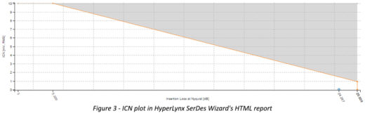
As shown in Figure 2, ICN is plotted against IL at Nyquist frequency of the channel’s operation and is measured in mV, root mean square (RMS). Similar to ICR, ICN allows for tradeoff between loss and crosstalk.
As we look deeper into COM methodology, you might be interested in reading this article or rereading our 2016 DesignCon Best Paper award winner.


Comments