Back side cap mounting
Earlier this year I wrote an article on maximizing capacitor effectiveness. I have since received a number of inquiries on mounting capacitors directly to a power via on the opposite side of the board from the IC. This is actually a fairly common design practice that I have seen on many boards. And, the question is, is this better than mounting the capacitors around the outside of the IC on the top side of the board? What do you think?
It is a question easily answered by spending a few minutes in the PDN Editor in LineSim. If you don’t have a license for HyperLynx PI, you can try it out for free in the HyperLynx Virtual Lab:
http://www.mentor.com/pcb/product-eval/hyperlynx-online-trial
It seems like the best place to mount a capacitor would be directly to a power via, as it is the closest you an get to those power pins. Will that always be better than mounting the capacitor on the same side of the board as the IC? Well, like anything else in signal and power integrity, it depends. In this case, the answer depends on where in the stackup your power/ground plane pair lies. Using the same example stackup that I used in the above-mentioned article, I used the PDN editor in LineSim to look at the mounted impedance of a 220nF 0402 capacitor mounted 1 inch away from the power pin on the top of the board, and also mounted directly to the power via on the opposite side of the board. With the power/ground plane pair closest to the top (VCC1/GND1 in the reference stackup), the capacitor mounted an inch away on the top actually exhibited a much lower impedance than the capacitor directly connected to the power via on the opposite side of the board. This is shown in the pic below: the impedance of the top-side cap is shown in yellow, while the cap connected to the power via is shown in pink.
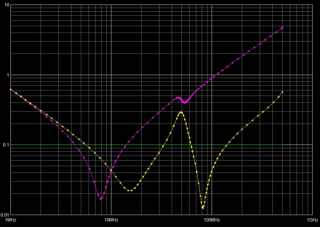
That may seem non-intuitive, since the opposite-side cap is only 62 mils (the board thickness) away from the IC, whereas the same-side cap is 1000 mils away! But the key factor is inductance, not distance. Even if we use an 0402 cap and via-in-pad, the distance between the mounting vias is still 40 mils. Compared to the 3-mil spacing between the planes, that creates a much larger loop area, and much higher inductance. The plane-pair connection is much lower inductance, so much so that even for a much longer connection distance, it still creates a lower-impedance connection for the capacitor.


Comments
Leave a Reply
You must be logged in to post a comment.
Via that connects capacitor to the pin can provide noise inside network and work like antena, so you can have problems with EMC tests.
Could you show your model used pleased
regards
Hi Andrew–
The details of the simulation are included in the article referenced in this blog. The article shows a picture of the stackup, and in this case the capacitor was mounted using via-in-pad. It is a standard 0402 cap, with ESL set to ‘Auto’ and ESR = 21mOhm.